 TechFuel HQ
Access ports take end devices untagged and stamp them with a PVID, while only switch-to-router links and the Proxmox uplink run as tagged trunks. OPNsense terminates each VLAN subinterface, hands out DHCP, and matches rules top to bottom, so blocks must precede passes. Nothing works until vlan-filtering=yes is set last on MikroTik and vmbr0 is ticked VLAN aware.
By LK Wood IV · Updated 2026-07-12 · ~15 min read · St. Louis County, MO
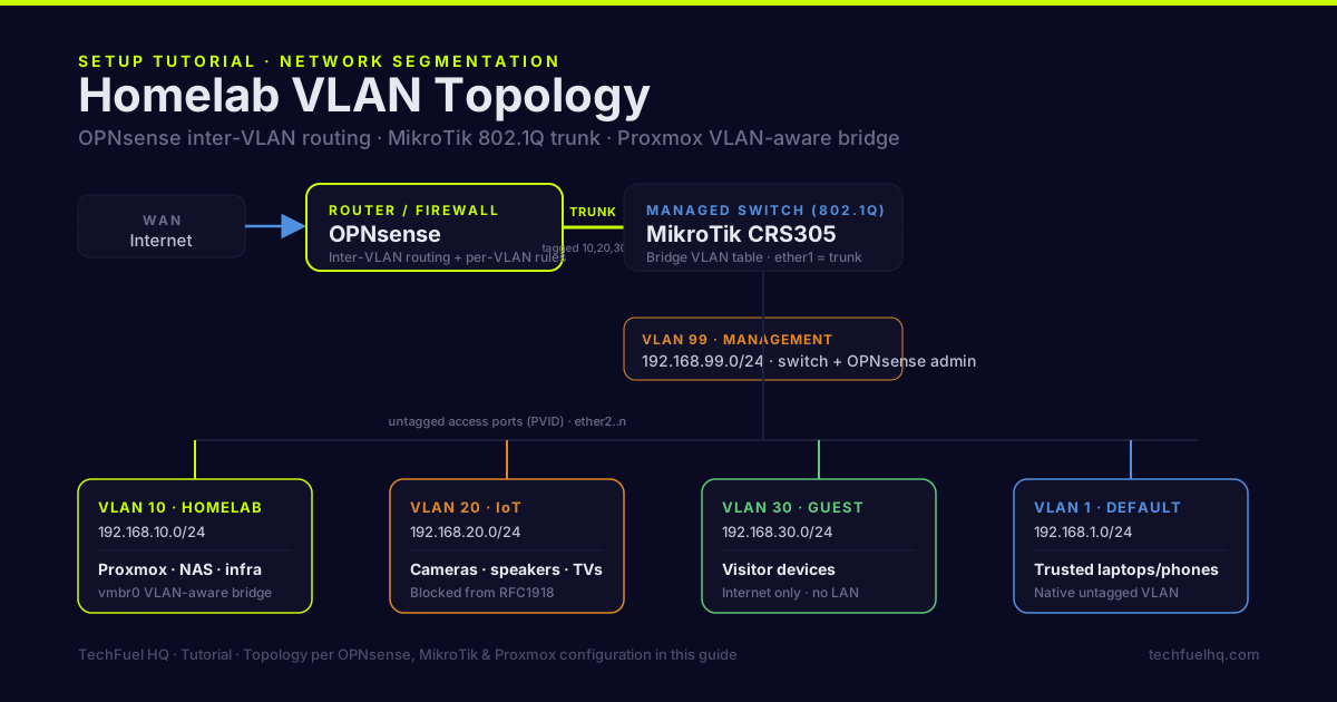
A flat network — every device sharing one /24 subnet — is fine right up until it isn’t. It stays fine while everything on it is trusted. It stops being fine the day you plug in a smart TV whose firmware stopped getting patches in 2022, or a doorbell camera phoning home to a cloud you’ve never audited, or you want a guest to have Wi-Fi without also having a clear path to your NAS. On a flat network, every device can talk to every other device. Segmentation is how you take that away without unplugging anything.
VLANs are the tool. One managed switch, one router that can route between the segments, and you can carve that single flat network into as many isolated lanes as you want — IoT that can reach the internet but not your Proxmox host, a guest network walled off from everything local, a management VLAN only your admin laptop can touch. This guide walks the whole thing end to end for the most common homelab stack: OPNsense doing the routing and firewalling, a MikroTik managed switch doing the tagging, and Proxmox carrying VLANs to VMs and containers over a single cable. The concepts transfer to UniFi, pfSense, or a $30 Netgear smart switch — only the menus change.
Before the menus, though, one diagram earns its keep more than any other. Almost every VLAN problem I’ve helped someone debug came down to not having a mental model of what physically happens to a frame on the wire — specifically, why some ports are “tagged” and some are “untagged,” and why mixing that up quietly breaks everything. So we start there.
Read that diagram twice if you need to. The single most common VLAN mistake is treating a device port as “tagged” — it isn’t. End devices connect to untagged (access) ports; only links between network gear are tagged (trunk) ports. A Proxmox host is the exception that proves the rule: because it hosts guests on many VLANs, its uplink is a trunk, and Proxmox itself handles the per-guest tagging internally.
Why segment your network
IoT isolation is the reason most people start. Smart TVs, cameras, speakers, robot vacuums — cheap devices with firmware that stops getting security updates the moment the next model ships. Put them on their own VLAN with a firewall rule that blocks them from reaching your trusted network, and a compromised camera can still phone home to its cloud, but it can’t pivot to your NAS or scan your Proxmox management interface. If you’re properly paranoid, you also block IoT devices from reaching each other, so one bad device can’t recruit the others.
A guest network that’s actually isolated. Visitors get internet, full stop — no visibility into your file shares, your Home Assistant, or your admin panels. A guest VLAN with a block-all-local rule does this cleanly, and you never have to hand out (or later change) your real Wi-Fi password.
A management VLAN for the things that run everything. Proxmox web UIs, switch management IPs, IPMI/iKVM, UPS network cards — the interfaces that, if reached by the wrong device, hand an attacker the keys. Lock them to a VLAN only your admin machine can enter.
Separation of services. Production VMs and lab/dev VMs on different VLANs, with outbound rules per segment: production can only reach the specific destinations it needs; the dev VLAN can go anywhere but can’t touch production. This is where a homelab starts behaving like a real network, and it’s genuinely good practice to learn on hardware you own.
Plan the VLANs before you touch a menu
Ten minutes on paper saves an hour of “why can’t this ping that.” Decide your VLAN IDs, subnets, and the one-line purpose of each before you log into anything:
| VLAN ID | Name | Subnet | Purpose |
|---|---|---|---|
| 1 | Default | 192.168.1.0/24 | Native/untagged VLAN — leave it mostly empty |
| 10 | Homelab | 192.168.10.0/24 | Proxmox nodes, NAS, homelab infrastructure |
| 20 | IoT | 192.168.20.0/24 | Smart devices, cameras, Zigbee/Z-Wave gateways |
| 30 | Guest | 192.168.30.0/24 | Visitor devices, fully isolated |
| 99 | Management | 192.168.99.0/24 | Switch mgmt IPs, OPNsense admin, IPMI |
The IDs are arbitrary but conventions help future-you: 10/20/30/40 for user VLANs, 99 for management, and VLAN 1 left alone. Don’t put anything important on VLAN 1. It’s the default native VLAN, it carries untagged traffic that lands on it by accident, and every switch treats it specially — using it for real devices is how “untagged frames leaked between segments” bugs happen.
Each VLAN above gets a full /24, which is 254 usable hosts — far more than a home segment will ever need, and the simplicity is worth the wasted address space. If you’d rather carve a block into tidier segments or check the usable host range for a given prefix, the subnet & CIDR calculator works out the network, broadcast, and host ranges for any CIDR.
With the plan on paper, the next question is the one that trips people up: once every VLAN is isolated, what is actually allowed to talk to what? Draw that as a grid and the entire firewall policy becomes obvious.
| FROM ↓ / TO → | Trusted | Homelab | IoT | Guest | Mgmt | Internet |
|---|---|---|---|---|---|---|
| Trusted | self | allow | allow | block | block | allow |
| Homelab | allow | self | allow | block | block | allow |
| IoT | block | block | self* | block | block | allow |
| Guest | block | block | block | block | block | allow |
| Mgmt | allow | allow | allow | allow | self | allow |
The rest of this guide is just teaching your three boxes to enforce that grid. OPNsense routes and filters (the colored cells above). The MikroTik switch tags and untags (the frame lifecycle up top). Proxmox carries the whole set of VLANs to your VMs over one cable.
OPNsense: routing and the firewall rules
OPNsense is where the isolation matrix becomes real. It terminates every VLAN, hands out DHCP on each, and enforces the pass/block rules.
Create the VLAN interfaces
Open Interfaces → Other Types → VLAN. For each VLAN:
- Parent interface: your LAN NIC (e.g.,
igc1) - VLAN Tag: the VLAN ID (e.g.,
10) - Description: Homelab, IoT, Guest, etc.
Then assign them under Interfaces → Assignments: add each subinterface (igc1.10, igc1.20, igc1.30, igc1.99) as a new interface and rename to something legible — HOMELAB, IOT, GUEST, MGMT. This assignment step is easy to forget, and until you do it the interface has no IP and routes nothing.
Give each VLAN an IP and DHCP
For each assigned interface (e.g., Interfaces → HOMELAB): Enable, IPv4 Config Type Static, address 192.168.10.1/24. That .1 is the VLAN’s gateway. Repeat per VLAN.
Then Services → DHCPv4 → [HOMELAB]: enable it and set a range like 192.168.10.100–192.168.10.199. Do the same for IoT (.20.100–200) and Guest (.30.100–200). The Management VLAN can stay static-only if you prefer to hand-assign admin addresses.
Write the firewall rules
Firewall → Rules, per interface tab. OPNsense evaluates rules top to bottom, first match wins — order is not cosmetic, it’s the whole logic. Translating the matrix:
# IoT tab
Block   IoT net  ->  RFC1918 (all private ranges)   # can't reach any other LAN
Pass    IoT net  ->  any                             # internet is fine
# Guest tab
Block   Guest net  ->  192.168.0.0/16 + 10.0.0.0/8   # no local anything
Pass    Guest net  ->  any                           # internet only
# Homelab tab
Pass    Homelab net  ->  any                         # trusted infrastructure
# Management tab (strict)
Block   any non-MGMT source  ->  MGMT net            # nothing else reaches mgmt
Pass    MGMT net  ->  any                            # admins reach everything
The block-before-pass ordering on IoT and Guest is the part people get wrong. Put a pass any above the block and the block never runs — the first match already let the traffic through. If a VLAN can reach things it shouldn’t, this ordering is the first place to look.
MikroTik: bridge VLAN filtering (do this the modern way)
Here is where a lot of older guides — and the previous version of this one — will steer you wrong, so read this section carefully. On a CRS3xx-class MikroTik switch, VLANs are not configured by creating /interface vlan objects on a physical port. That approach is exactly the misconfiguration MikroTik’s own documentation warns against; it produces switches that “work” until they mysteriously don’t, because traffic is being software-switched through the CPU instead of hardware-offloaded in the switch chip. The correct modern method is bridge VLAN filtering: one bridge, a VLAN table that says which ports are tagged and untagged for each VLAN, and a single switch to turn filtering on.
One hard warning first: enabling vlan-filtering=yes is the last step, and doing it wrong locks you out of the switch. Configure everything else, make sure your own access port and management VLAN are in the table, and ideally have serial/console access before you flip that switch. If you enable filtering over the very connection you’re configuring and the management VLAN isn’t set up correctly, the session dies mid-command.
Build the bridge with filtering off, add the ports:
/interface bridge
add name=bridge1 vlan-filtering=no
# ether1 = trunk uplink to OPNsense (no pvid; it carries tags)
/interface bridge port
add bridge=bridge1 interface=ether1
# ether2 = access port for a Proxmox node on VLAN 10
add bridge=bridge1 interface=ether2 pvid=10 ingress-filtering=yes frame-types=admit-only-untagged-and-priority-tagged
# ether3 = access port for an IoT hub on VLAN 20
add bridge=bridge1 interface=ether3 pvid=20 ingress-filtering=yes frame-types=admit-only-untagged-and-priority-tagged
The pvid on an access port is what stamps incoming untagged frames onto the right VLAN — it’s the “IN” step from the frame-lifecycle diagram. frame-types=admit-only-untagged-and-priority-tagged tells that port to reject already-tagged frames, so a device can’t lie about its VLAN.
Fill in the VLAN table — which ports are tagged vs untagged per VLAN:
/interface bridge vlan
# ether1 (trunk) is tagged for every VLAN; bridge1 is tagged so the CPU can reach mgmt
add bridge=bridge1 tagged=bridge1,ether1 untagged=ether2 vlan-ids=10
add bridge=bridge1 tagged=bridge1,ether1 untagged=ether3 vlan-ids=20
add bridge=bridge1 tagged=bridge1,ether1 vlan-ids=30
add bridge=bridge1 tagged=bridge1,ether1 vlan-ids=99
Put the switch’s own management IP on VLAN 99, then enable filtering last:
/interface vlan
add interface=bridge1 name=vlan99 vlan-id=99
# this /interface vlan is correct - it is on the BRIDGE, giving the switch itself an L3 presence on VLAN 99
/ip address
add address=192.168.99.2/24 interface=vlan99
/ip route
add dst-address=0.0.0.0/0 gateway=192.168.99.1
# everything is staged - now turn filtering on (do this from console if you can)
/interface bridge
set bridge1 vlan-filtering=yes
Note the distinction that trips everyone up: /interface vlan is wrong on a physical ether port (that’s the software-switching trap) but right on the bridge itself, where it gives the switch a routable management address on VLAN 99. Same command, completely different meaning depending on where you point it.
Proxmox: one VLAN-aware bridge, every VLAN
Proxmox is the elegant part. You do not create a bridge per VLAN. You make one bridge VLAN-aware and tag each guest individually.
Datacenter → pve01 → System → Network:
- Select your bridge (
vmbr0) - Tick VLAN aware
- Save, then Apply Configuration
The bridge’s physical NIC (e.g., eno1) plugs into a trunk port on the switch — the same kind of tagged port as the OPNsense uplink, carrying every VLAN. Then, when creating or editing any VM/LXC, in the network tab:
- Bridge:
vmbr0 - VLAN Tag:
10(for the Homelab VLAN)
The guest gets an untagged interface that Proxmox silently places on VLAN 10. The VM has no idea — it’s the frame-lifecycle “OUT” step happening inside the host. Want a guest reachable from two VLANs (Home Assistant is the classic case — user access on the trusted VLAN, device discovery on IoT)? Add a second network device with a different VLAN Tag. One caveat worth burning into memory: don’t put the Proxmox management interface itself on a VLAN unless you’re sure the config is right and you have console/iKVM access. A VLAN typo on the management interface locks you out of the very web UI you’d use to fix it.
The thing that quietly breaks: mDNS and multicast
You will finish all of the above, test it, watch IoT get blocked from your LAN, feel great — and then discover you can no longer cast to the living-room TV, AirPlay to a HomePod, or print from your laptop. Nothing is broken. This is VLANs working exactly as designed, and it’s the single most common “why did I even do this” moment.
Service discovery — Chromecast, AirPlay, HomeKit, Spotify Connect, AirPrint, most network printers — relies on mDNS (multicast DNS) on UDP port 5353. Multicast is local-segment-only by design; it does not cross VLAN boundaries. So your phone on the trusted VLAN literally cannot see the Chromecast sitting on the IoT VLAN, even if a firewall rule would allow the connection, because the discovery packets never make the trip.
The fix is an mDNS reflector (also called a repeater): a service that listens for those multicast announcements on one VLAN and rebroadcasts them onto the others, so devices on different segments can discover each other. On OPNsense:
System → Firmware → Plugins— installos-mdns-repeater, then reload the page.Services → mDNS Repeater— enable it and select the VLANs that need to see each other (typically Trusted and IoT).Firewall → Rules— add a rule allowing UDP 5353 from each participating VLAN. The plugin only relays the announcements; without the firewall pass rule, the actual connection that follows discovery is still blocked. This is the step people miss.
A reflector is a passive relay, not a bidirectional proxy, so occasionally a chatty device needs mDNS allowed in both directions — but for casting, AirPlay, HomeKit, and printers, enabling the repeater on the two relevant VLANs plus the UDP 5353 rule is the whole fix. Decide up front which VLANs actually need cross-discovery; you don’t want to reflect your Guest network’s multicast into your trusted LAN.
Test that isolation is real
Configuration that isn’t verified is a guess. Prove each cell of the matrix:
# From an IoT device (or a VM tagged onto VLAN 20)
ping 1.1.1.1        # PASS - internet allowed
ping 192.168.1.1    # FAIL - blocked from trusted LAN
ping 192.168.10.10  # FAIL - blocked from homelab
# From a laptop on the trusted VLAN
ping 192.168.10.10  # PASS - trusted can reach a Proxmox node
# From the IoT VLAN again
ping 192.168.10.10  # FAIL - IoT stays walled off
If an inter-VLAN test fails when it should pass (or passes when it should fail), work down this list in order:
- OPNsense rule order — block before pass, first match wins. This is the cause about 70% of the time.
- DHCP scope — is the device actually getting an address in the right VLAN’s range? Wrong subnet means wrong VLAN, upstream of any rule.
- Switch VLAN table — does the untagged port assignment match the VLAN ID? And did you remember
vlan-filtering=yes?
The mistakes that cost the most time
vlan-filtering=yes never got set. You built the entire bridge VLAN table, everything looks configured, and no segmentation is enforced — because filtering is still off and the table is inert. This is a silent failure: nothing errors, it just doesn’t work. It’s the first thing to check on a MikroTik that “isn’t segmenting.”
A pass-any rule sitting above the block rule. OPNsense reads top to bottom and stops at the first match. If IoT can still reach your LAN, a broad pass rule is almost certainly shadowing your block. Reorder it.
Forgetting to assign the VLAN interface in OPNsense. Creating the subinterface under Interfaces → Other Types → VLAN is only half the job — it does nothing until you also add it under Interfaces → Assignments and give it an IP.
The trunk isn’t tagged for a VLAN that needs it. If VLAN 20 traffic never reaches OPNsense, the trunk port (and the bridge) probably isn’t in VLAN 20’s tagged list. Every VLAN that has to reach the router must be tagged on the uplink.
Management on a VLAN with no escape hatch. Putting a switch or Proxmox host’s management interface on a VLAN is good practice — right up until a VLAN typo locks you out of the only interface you could fix it from. Always keep a console path: serial for the switch, iKVM or a directly attached keyboard/monitor for Proxmox.
Blaming VLANs when it’s really mDNS. If casting or printing stops after segmentation, you didn’t break routing — you did it correctly, and now discovery needs an mDNS reflector (above). Chasing firewall rules for this is a time sink.
VLANs need a capable router to enforce inter-VLAN firewall rules — the segmentation lives at the switch, but the policy lives at the firewall. The OPNsense setup guide covers building that firewall from scratch, and the homelab firewall & router comparison helps pick between OPNsense, pfSense, and MikroTik for the routing role. For the physical layer — managed switches and cabling — the 10GbE home networking guide covers hardware selection.
Sources
- IEEE 802.1Q (VLAN tagging standard) – the tag structure used in the frame-lifecycle diagram: a 4-byte tag (TPID 0x8100, PCP, DEI, and a 12-bit VID with valid range 1-4094), extending the maximum frame from 1518 to 1522 bytes.
- MikroTik RouterOS: Bridge VLAN Table – official RouterOS reference for bridge VLAN filtering, tagged trunk and untagged access port assignments,
pvid,frame-types, and thevlan-filteringswitch. The source for the “do it the modern way” rewrite. - OPNsense manual: VLAN and LAGG Setup – official OPNsense steps for creating tagged VLAN interfaces, assigning them, and configuring inter-VLAN routing.
- OPNsense manual: Multicast DNS Proxy – official documentation for the
os-mdns-repeaterplugin used to make Chromecast, AirPlay, HomeKit, and printers discoverable across VLANs, including the UDP 5353 firewall requirement. - Proxmox VE wiki: Network Configuration – official Proxmox documentation for VLAN-aware Linux bridges and per-guest VLAN tags.
Frequently asked questions
Do I need a managed switch for VLANs?
What's the difference between a tagged and untagged port?
Can I set up VLANs without a router that supports them?
Will VLANs slow down my network?
How do I configure Proxmox to use VLANs?
Why did my Chromecast, AirPlay, or printer stop working after I set up VLANs?
Evidence ledger
- Last updated
- Methodology
- This tutorial was written and edited by Lowell K. Wood IV in St. Louis County, MO. Specs, prices, commands, and version numbers are drawn from the official vendor, reseller, and project documentation current on the date above, and were verified before publishing. First-person hardware claims appear only where the article shows a verifiable artifact — a photo, receipt, or measurement — or links to the TechFuelHQ Open Bench Datasets. Every fact is human-verified against its cited source before publishing; AI assists with first-draft structure and source-gathering, not with the verdict. Full editorial standard: methodology.
- Update log
- 2026-07-25 — Last reviewed and updated.
- Corrections
- Spotted an error or stale price? Email hello@techfuelhq.com. Confirmed corrections are added to the update log above.